This is the first installment in a series to provide more background information on AriesVerb. There already exists the manual (see download page), but the manual is intended to be a reference. It tells you where the controls are and how to operate them, but does not go much into the «why» of things. That’s where this tutorial starts off.
The first chapter is about maybe the most enigmatic aspect of AriesVerb: The feedback matrix and it’s controls. The chapter is split in two parts. This first part (this part) is the theory and the second part will be the practice.

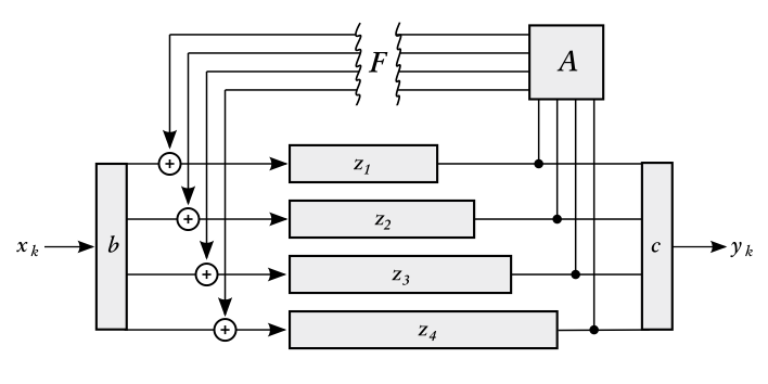
Fig. 1: Schematic of a Feedback Delay Network. Delay lines at z1…z4; feedback matrix at A.
AriesVerb operates as an FDN (Feedback Delay Network), a schematic of which is shown in figure 1. The concept should be easy to get: There are a number of parallel delay lines, four in case of AriesVerb (unless you enable multitap-mode, then there are effectively 16). Any delay line can feed back into any other via the big feedback matrix. Simple.
Or not so simple. The entries in the matrix are tightly constrained if the system is to be stable. You cannot just put any old values into the matrix (or, you can, but then in all likelihood the thing will diverge and the plugin will be auto-muted by the host faster than you can say ‹Oh, snap›).
Therefore the choice needs to be limited to useful matrices which are controllable, and the way this is handled in AriesVerb—and has always been since the beginning—is to focus exclusively on rotation matrices.
The matrix controls

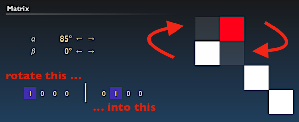
Fig. 2: The matrix editor page in AriesVerb.
The above screenshot is taken straight out of the AriesVerb manual. There is a rotation angle control at position ![]() . Then there is a control that looks like a row with 8 numbers, split into two groups of four numbers each at position
. Then there is a control that looks like a row with 8 numbers, split into two groups of four numbers each at position ![]() —this is the rotation plane control. Finally, there is an abstract display of the resulting matrix at position
—this is the rotation plane control. Finally, there is an abstract display of the resulting matrix at position ![]() . The matrix is layed out such that the route from delay line
. The matrix is layed out such that the route from delay line ![]() is found at column
is found at column ![]() , row
, row ![]() :
:
![Rendered by QuickLaTeX.com \[\begin{array}{cccc} 1\rightarrow1 & 2\rightarrow1 & 3\rightarrow1 & 4\rightarrow1 \\ 1\rightarrow2 & 2\rightarrow2 & 3\rightarrow2 & 4\rightarrow2 \\ 1\rightarrow3 & 2\rightarrow3 & 3\rightarrow3 & 4\rightarrow3 \\ 1\rightarrow4 & 2\rightarrow4 & 3\rightarrow4 & 4\rightarrow4 \end{array} .\]](http://ariescode.com/wordpress/wp-content/ql-cache/quicklatex.com-b30b5ffcfcc429f7e564437d9b01dbf8_l3.png)
The amount of feedback is color-coded: White represents positive feedback and red represents negative feedback.
Of Angles …
You may get the impression that this tutorial seems to become more a treatise on geometry then about sound. And in some way, it is! In AriesVerb, geometry and sound are fundamentally linked. To quote a 19th century mathematician:
… for geometry, you know, is the gate of science, and the gate is so low and small that one can only enter it as a little child.
William K. Clifford
But I digress. As said earlier, AriesVerb is built on rotation matrices, so we need some way to control them. At the end of the day, the job of the matrix is to shuffle and mix the delay lines with one another. How do angles and planes relate to this?
In one sentence, the angles control the amount of intermixing, while the plane decides which delay lines take part in the intermixing. The rest is details. You can stop here and, armed with this knowledge, go on experimenting. Or you can read on for more theory.
| If the rotation angles are | then the choice of rotation plane | and the resulting matrix is |
|---|---|---|
| both |
does not matter | the identity matrix. |
| both |
does not matter | the central inversion. |
| Otherwise | matters | one of the many various special orthogonal matrices. |

Fig. 3: Display of the identity matrix (left); display of the central inversion (right).
In the table above I have listed the three fundamental cases to consider. If both angles are at ![]() , there is no rotation, and no mixing. The matrix simply sends each line to itself. In this configuration, AriesVerb reduces to an array of parallel comb filters. On the other hand, if both angles are at
, there is no rotation, and no mixing. The matrix simply sends each line to itself. In this configuration, AriesVerb reduces to an array of parallel comb filters. On the other hand, if both angles are at ![]() , the situation is almost the same except that the feedback is negative. For any other choice of rotation angles, the outcome depends on the particular choice of rotation plane, so we need to explain that now.
, the situation is almost the same except that the feedback is negative. For any other choice of rotation angles, the outcome depends on the particular choice of rotation plane, so we need to explain that now.
… And Planes
It should be obvious that we not only need a way to specify how much rotation we want, but also, which way ‹round the rotation should go. In other words, from which delay lines shall be taken and to which delay lines shall be given. This is the purpose of the rotation plane control.

Fig. 4: Example of a simple rotation of almost 90°.
The rotation plane is spanned by two vectors, let’s call them ![]() and
and ![]() . These are shown in the user interface on the left and on the right in the rotation plane control. Each vector has four elements, representing the four delay lines. Any delay line can be selected into either
. These are shown in the user interface on the left and on the right in the rotation plane control. Each vector has four elements, representing the four delay lines. Any delay line can be selected into either ![]() or
or ![]() , but not into both at the same time. Also, the vectors must not be empty. Then:
, but not into both at the same time. Also, the vectors must not be empty. Then:
The matrix shall be a rotation matrix of such kind that it exactly rotates
into
when
.
And that’s all there is to it. You can let that sink in for while. Of course, the devil is in the details. What happens when more than one delay line is selected? What does the ![]() angle do? Slowly! First let’s examine the example shown above—which is the most simple example possible—and see if the matrix does as advertised: rotate delay line 1 into delay line 2. One way of looking at this is to recall the matrix layout from above and follow the routing plan. We have
angle do? Slowly! First let’s examine the example shown above—which is the most simple example possible—and see if the matrix does as advertised: rotate delay line 1 into delay line 2. One way of looking at this is to recall the matrix layout from above and follow the routing plan. We have
![Rendered by QuickLaTeX.com \[\begin{array}{cccc} & \color{red} 2\rightarrow1 & & \\ 1\rightarrow2 & & & \\ & & 3\rightarrow3 & \\ & & & 4\rightarrow4 \end{array} .\]](http://ariescode.com/wordpress/wp-content/ql-cache/quicklatex.com-81f3272dbf8d3d2494a1c417f921eb89_l3.png)
The signal from line 1 goes to line 2, and the signal from line 2 goes back to line 1, but with a sign flip along the way. Only after making another round does the signal come back with the original phase. In total, four feedback cycles are necessary to get back to square one, which corresponds to a rotation of ![]() .
.
You might have noticed that in the example above, ![]() is not exactly
is not exactly ![]() , but it is slightly off at
, but it is slightly off at ![]() . This introduces a little amount of scattering, because the routes
. This introduces a little amount of scattering, because the routes ![]() and
and ![]() are non-zero, if only very slightly so. This is an example of a deliberate «imperfectness». In this case, the combined result will be a low-frequency beating, and the time of the beat can be calculated. The error of
are non-zero, if only very slightly so. This is an example of a deliberate «imperfectness». In this case, the combined result will be a low-frequency beating, and the time of the beat can be calculated. The error of ![]() needs
needs ![]() feedback cycles to make one revolution. Assuming that the time base is, say, 50 ms, then the beat would have a period of 3.6 seconds.
feedback cycles to make one revolution. Assuming that the time base is, say, 50 ms, then the beat would have a period of 3.6 seconds.

Fully Dense Matrices
Still with me? Good. We will now go back to the configuration as shown in the beginning in figure 2. There we have a fully dense matrix of the type typically used for plate reverb algorithms, except that multi-tap has been disabled to emphasize the 4×4 structure. In this example, the rotation angles are ![]() ,
, ![]() , and all four delay lines are selected into the rotation plane, with two on each side.
, and all four delay lines are selected into the rotation plane, with two on each side.

The resulting matrix is not only fully dense, it would also be perfectly homogeneous (all elements at the same level at ![]() ) if not for another small imperfectness that is introduced by a non-zero
) if not for another small imperfectness that is introduced by a non-zero ![]() angle. This imperfectness is visible as slightly different levels of brightness in some squares. But I digress. Remember the gospel?
angle. This imperfectness is visible as slightly different levels of brightness in some squares. But I digress. Remember the gospel?
The matrix shall be a rotation matrix of such kind that it exactly rotates
into
when
.
And below is the proof that this is really true.
![Rendered by QuickLaTeX.com \[\begin{array}{cc} \vec{v} \, \begin{array}{|c|} -1 \\ 0 \\ 0 \\ -1 \end{array} \leftarrow & \begin{array}{|cccc|} \hline \sfrac{1}{2} & -\sfrac{1}{2} & -\sfrac{1}{2} & -\sfrac{1}{2} \\ \sfrac{1}{2} & \sfrac{1}{2} & -\sfrac{1}{2} & \sfrac{1}{2} \\ \sfrac{1}{2} & -\sfrac{1}{2} & \sfrac{1}{2} & \sfrac{1}{2} \\ -\sfrac{1}{2} & -\sfrac{1}{2} & -\sfrac{1}{2} & \sfrac{1}{2} \\ \hline \end{array} \\[12pt] & \uparrow \\ & \begin{array}{cccc} \hline 0 & 1 & 1 & 0 \\ \hline \multicolumn{4}{c}{\vec{u}} \end{array} \end{array}\]](http://ariescode.com/wordpress/wp-content/ql-cache/quicklatex.com-8c8ffd9fb233357f7908c2f8a4bd5e97_l3.png)
As was said earlier, the columns of the matrix correspond to the input lines and the rows correspond to the output lines. So, if the input equals ![]() , the output should be
, the output should be ![]() . To check that this is true, multiply each column with the corresponding element of
. To check that this is true, multiply each column with the corresponding element of ![]() (which, in the above example, effectively singles out the middle columns), then add up everything horizontally. The result is indeed
(which, in the above example, effectively singles out the middle columns), then add up everything horizontally. The result is indeed ![]() .
.
The next installment is going to present some concrete examples. It will show the required settings to make some typical FDN matrices: the Householder matrix, the Stautner & Puckette matrix, some matrices equivalent to figure-eight topology, permutation matrices, and others. Since comments are disabled on this blog, you are invited to take any questions or discussions over to the AriesCode forum on KvR.
FQA (frequently questioned answers)
- What is the action on any other vectors besides the selected ones?
- That is a consequence of the fact that the matrix must be a rotation. The matrix is always unambiguously determined by rotation angle and plane.
- What happens when
 is negative?
 - The same as if
 and
and  were swapped and
  was positive. Specifically, if
  , then the resulting matrix will rotate
  into
into  .
. - What does
 do?
do? - See the next installment.
